- 您现在的位置:买卖IC网 > Sheet目录201 > ABJ3638609 (Panasonic Electric Works)SWITCH TURQ SPST LEAF SILV WIRE
ABJ1,2,3,4,5
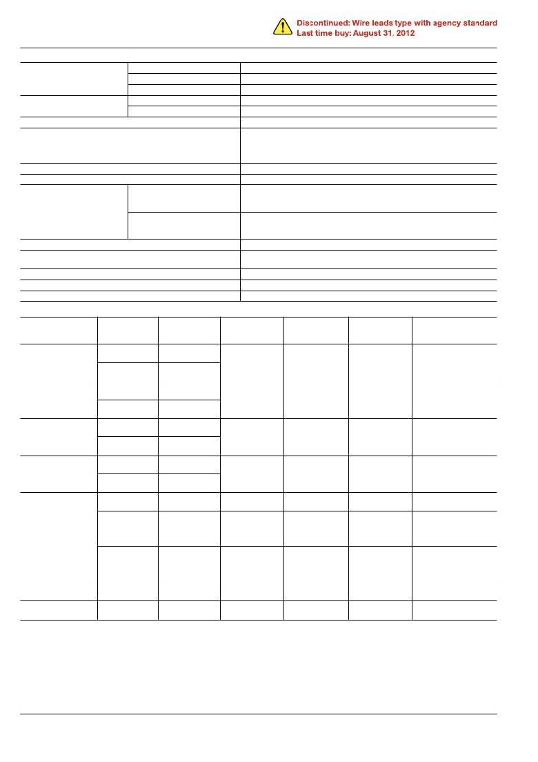
2. Characteristics
Mechanical life
(O.T.: Speci?ed value)
Electrical life at rated load
(O.T.: max.)
Insulation resistance
Dielectric strength
Leaf lever, Long stroke type Min. 5 × 10 5 (at 60 cpm)
Wire leads (right & left side type) Min. 3 × 10 5 (at 60 cpm)
Other types Min. 10 6 (at 60 cpm)
AgNi alloy contact type Min. 3 × 10 4 (at 20 cpm)
AgNi alloy + Au clad contact type Min. 10 5 (at 20 cpm)
Min. 100 M ? (at 500 V DC insulation resistance meter)
Between non-continuous terminals
Between each terminal and other exposed metal parts
Between each terminal and ground
Vibration resistance (Pin plunger type)
Shock resistance (Pin plunger type)
Silver contact type
600 Vrms
1,500 Vrms
1,500 Vrms
10 to 55 Hz at single amplitude of 0.75 mm (Contact opening max. 1 msec.)
Min. 294 m/s 2 {30 G} (Contact opening max. 1 msec.)
Dust protected type (IP50): Max. 50 m ?
Immersion protected type (IP67): Max. 100 m ?
Contact resistance (Initial)
Gold clad contact type
(By voltage drop 1 A 6 to 8 V DC)
Dust protected type (IP50): Max. 100 m ?
Immersion protected type (IP67): Max. 150 m ?
(By voltage drop 0.1 A 6 to 8 V DC)
Allowable operating speed (at no load)
Max. operating cycle rate (at no load)
Ambient temperature
Unit weight
Water resistance
3. Operating characteristics
1 to 500 mm/sec.
Other type: 120 cpm
Long stroke type: 60 cpm
–40 ° C to +85 ° C
Approx. 0.5 g (IP50 type)
IP67 (Wire leads type)
Type of actuator
Pin plunger
Hinge lever
Simulated roller lever
Roller lever
Leaf lever
Long stroke type
Operating force,
Max.
1.23N
1.96N
0.39N
0.64N
0.39N
0.64N
0.39N
0.64N
0.98N
1.27N
1.76N
1.27N
2.45N
Release force,
Min
0.15N
0.25N
0.029N
0.049N
0.029N
0.049N
0.029N
0.049N
0.20N
0.22N
0.26N
0.29N
0.20N
Pretravel,
Max. mm
0.6
3.0
3.0
3.0
6.0
2.6
2.6
6.0
—
Movement
differential,
Max. mm
0.12
0.5
0.5
0.5
1.0
0.5
0.5
1.0
0.5
Overtravel,
Min. mm
0.25
0.5
0.5
0.5
2.5
1.4
1.4
2.5
2.0
Operating position,
mm
Mounting hole: 1.2
5.5 ± 0.2
Mounting hole: 2.3
7.0 ± 0.2
Mounting hole: 1.2
6.8 ± 1.0
Mounting hole: 2.3
8.3 ± 1.0
Mounting hole: 1.2
9.8 ± 1.0
Mounting hole: 2.3
11.3 ± 1.0
Mounting hole: 1.2
13.1 ± 1.0
Mounting hole: 2.3
14.6 ± 1.0
Mounting hole: 3.0
16.0 ± 2.0
Fixed pin type
10.7 ± 0.7
Mounting hole: 3.0
16.25 ± 0.7
Fixed pin type
10.7 ± 0.7
Mounting hole: 3.0
16.25 ± 0.7
Mounting hole: 3.0
16.0 ± 2.0
2.5 ± 0.4
Note: The O.P. differs between the 1.2 mm and 2.3 mm dia. installation hole types.
Panasonic Corporation
Automation Controls Business Unit
industrial.panasonic.com/ac/e
AECTB1E 201201-T
发布紧急采购,3分钟左右您将得到回复。
相关PDF资料
ABL-9.8304MHZ-B2
CRYSTAL 9.8304MHZ 18PF HC49/US
ABLS-8.000MHZ-B2-T
CRYSTAL 8.000MHZ 18PF SMD
ABLS-LR-3.2768MHZ-T
CRYSTAL 3.2768MHZ 18PF LOW ESR
ABLS2-3.579545MHZ-D4Y-T
CRYSTAL 3.579545 MHZ 18PF SMD
ABLS3-9.8304MHZ-D4Y-T
CRYSTAL 9.8304 MHZ 18PF SMD
ABLSG-25.000MHZ-D-2-Y-F-T
CRYSTAL 25.000 MHZ 18PF SMD
ABM10-26.000MHZ-7-A15-T
CRYSTAL 26.000 MHZ 10PF SMD
ABM11-25.000MHZ-B7G-T
CRYSTAL 25.000 MHZ 10 PF SMD
相关代理商/技术参数
ABJ3638619
功能描述:基本/快动开关 SPST, NO, Leaf Lever, Wire
RoHS:否 制造商:Omron Electronics 触点形式:SPDT 执行器:Lever 电流额定值:5 A 电压额定值 AC:250 V 电压额定值 DC:30 V 功率额定值: 工作力:120 g IP 等级:IP 67 NEMA 额定值: 端接类型:Wire 安装:Panel
ABJ36436113
制造商:LG Corporation 功能描述:Cabinet Assembly
ABJ36503801
制造商:LG Corporation 功能描述:Cabinet Assembly
ABJ36503802
制造商:LG Corporation 功能描述:Cabinet Assembly
ABJ36503901
制造商:LG Corporation 功能描述:Cabinet Assembly
ABJ36509506
制造商:LG Corporation 功能描述:Cabinet Assembly
ABJ36509516
制造商:LG Corporation 功能描述:Cabinet Assembly
ABJ36509524
制造商:LG Corporation 功能描述:Cabinet Assembly